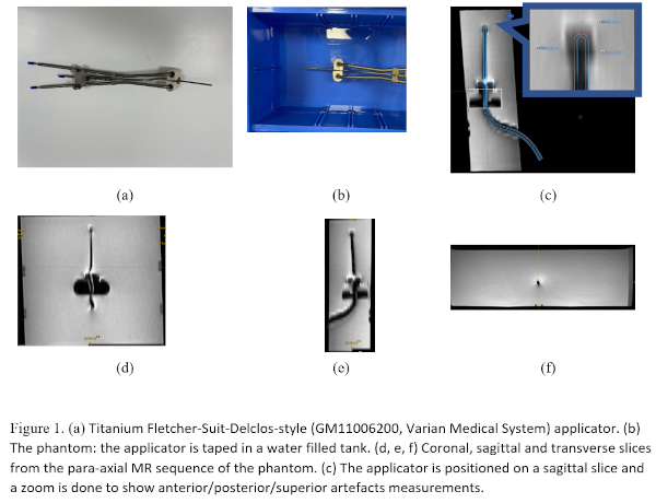
Copenhagen, Denmark
Onsite/Online

ESTRO 2022

Session Item

Imaging acquisition and processing
7000
Poster (digital)
Physics
Quantification of MRI signal artifacts from titanium intracavitary brachytherapy applicator
souha aouadi, Qatar
PO-1614

Abstract

Quantification of MRI signal artifacts from titanium intracavitary brachytherapy applicator
Authors:

souha aouadi1, Siji Nojin P.1, Suparna Chandramouli1, Tarraf Torfeh1, Rabih Hammoud1, Noora Al-hammadi1

1National Center for Cancer Care and Research, Radiation Oncology, Doha, Qatar

Show Affiliations
Purpose or Objective

MRI, which offers better soft tissues visualization compared to CT, is increasingly used to guide treatment in brachytherapy. Its use has, however, its own challenges such as geometric distortion and restrictive compatibility with magnetic materials. The latter is important when titanium applicators are used for cervical cancer patients. Due to the difference of magnetic susceptibility between the applicator and the surrounding tissues, the applicator is magnetized and produces a magnetic field that opposes the applied magnetic field, which distort the original magnetic field and results in metallic artefacts in the form of signal loss, signal pile-up and geometric distortion. The purpose of this study was to quantify the level of artifacts due to titanium applicator on 1.5T GE MRI simulator.

Material and Methods

Titanium Fletcher-Suit-Delclos-style (GM11006200, Varian Medical System) applicator set was used in this study (Fig 1.a). It was placed in a water filled tank to simulate a phantom (Fig 1.b) and scanned using the brachytherapy uterine protocol of our clinic. The acquired images were sagittal T2 cube (a voxel size of 0.39 × 0.39 × 1.2 mm3, a matrix size of 512 × 512 × 232, a repetition time TR = 2000 ms, an echo time TE = 59.67 ms, and a flip angle FA = 90°), para-coronal T2 propeller (a voxel size of 0.5 × 0.5 × 3 mm3, a matrix size of 512 × 512 × 15, TR = 1406.3 ms, TE = 82.08 ms, FA = 140°), para- axial T2 propeller (a voxel size of 0.39 × 0.39 × 3.29 mm3, a matrix size of 512 × 512 × 51, TR = 5319.7 ms, TE = 95.9 ms, and FA = 140°) (Fig. 1. d, e, f).

The tandem and ovoid geometries were projected from the Varian’s library of applicators into the MRI and were positioned manually to their location in the images by the physicist (Fig 1.c). A reference segmentation of the tandem was therefore extracted. The tandem, which appear with low intensities (signal loss), was segmented automatically on the MRI sequences by thresholding.

Dice, sensitivity, and Jaccard indices were computed between the reference segmentation and the MRI-based segmentation of the tandem in each MRI sequence. Distances were measured from the tandem tip to the MRI artifact edge in right/left/superior and anterior/posterior directions in the coronal and sagittal views respectively. Eclipse Brachytherapy Planning System (Version 16.1) was used for measurements.


Results

Table 1 shows the segmentation indices obtained for each MR sequence type of the brachytherapy protocol. The distances measured for MRI artifacts are displayed in table 1.  The sagittal 3D cube T2 MRI presented the smallest average artifacts whereas the highest average artifacts were obtained for the para-axial T2 MRI which is used for the contouring of the OARs and target.


Conclusion

In this study, we have characterized artifacts due to titanium brachytherapy applicators in multiple MR sequences at 1.5T. Future work will consist on optimizing the MR sequences to reduce the artifacts while preserving imaging time and contrast.