Copenhagen, Denmark
Onsite/Online

ESTRO 2022

Session Item

Imaging acquisition and processing
7000
Poster (digital)
Physics
Evaluating the geometric accuracy of the constructed Mid-P CT using mathematically deformed phantoms
Firass Ghareeb, Portugal
PO-1603

Abstract

Evaluating the geometric accuracy of the constructed Mid-P CT using mathematically deformed phantoms
Authors:

Firass Ghareeb1, Saber Sarbazvatan2, Joep Stroom3, Djamal Boukerroui4, Carlo Greco1

1Champalimaud Centre for the Unknown, Department of radiation oncology, Lisbon, Portugal; 2Institute for Systems and Robotics (ISR/IST), LARSyS, Instituto Superior TĂ©cnico, Universidade de Lisboa, Lisbon, Portugal; 3Champalimaud Centre for the Unknown, Department of radiation oncology, Lisbon , Portugal; 4Mirada Medical Ltd., ., Oxford, United Kingdom

Show Affiliations
Purpose or Objective

Mid position CT (Mid-P) is constructed from 4DCT using deformable image registration (DIR) to create a time-weighted mean position of anatomy during the respiratory cycle and is used for treatment planning leading to smaller PTVs. Since Mid-P applications are not commercially available yet, several RT centers are developing their own Mid-P applications using publicly available 4DCT DIR test datasets for evaluation.

Although the registration accuracy between phases for these datasets was verified by experts, they are still prone to human and registration errors. Furthermore, since none of the datasets provides the Mid-P CT of the dataset, they can only be used to test the registration step of the Mid-P construction procedure.

This work aims to generate deformable 4DCT phantoms and their corresponding ground-truth Mid-P CTs using mathematical models.

Material and Methods

A 4DCT phantom was created with MATLAB®, the phantom consists of 50 slices and 10 phases (512x512 slices with 1x1x2 mm3 voxel size).

The contour of a synthetic 4D organ was designed within the phantom according to the following 2D polar equation

Rθ=a+b(sin(θ) - cisin(θ)cos(θ) + dicos(θ))   Eq.1 

Where [6≤a≤8, -1≤b≤1.5, -3≤ci≤1, 1≤di≤2.5, i=slice number]

The contour was deformed through individual slices and phases by applying different values to the a, b, c and d coefficients of Eq.1, the values were chosen to achieve a smooth deformation 
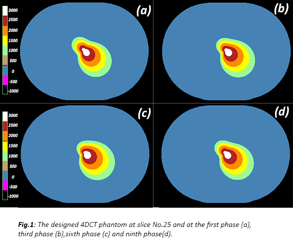
between consecutive phases and slices like human organs. The intensity values within the contour were assigned to five discrete gradual values (1000 - 3000 HU) following the same polar equation and coefficients (see Fig.1).


Since coefficients (a) and (b) are constants across phases, the radius Rθ of Eq.1 at any fixed angle (θ) depends linearly on the coefficients (a,b,ci,di). Thus, the ground-truth Mid-P contour in a slice is generated by using the mean coefficients of the 10 phases (a, b, mean(ci), mean(di)) in Eq.1. By repeating this to all slices we can create a time-weighted average contour of the organ.

The intensity values within the Mid-P contour were assigned similarly to the phantom. The created phantom was used to test a Mid-P automated research prototype (developed by Mirada Medical Ltd). The constructed Mid-P CT by the prototype was compared to the ground-truth Mid-P CT using root mean-squared error (RMSE) and the organ’s contour of the constructed Mid-P was compared to the ground-truth contour using Dice similarity coefficient (DSC) and Hausdorff distance.

Results

RMSE in the organ’s region=15.4 HU, DSC=0.98 and the 95th percentile Hausdorff distance=2 mm. Fig.2 shows a visual comparison between the ground truth and the prototype constructed Mid-P.

Conclusion

The generated mathematical phantom can be used by developers to test the geometric accuracy of the constructed Mid-P CT, it can also be used for commissioning the Mid-P applications when they are commercially available. The results of the evaluated prototype showed excellent matching with the ground truth.