A robust method for determining backlash of a multileaf collimator
PO-1510
Abstract
A robust method for determining backlash of a multileaf collimator
Authors: Antti Kulmala1, Anna Rintala2, Lauri Koivula2, Viljo Petäjä3, Mikko Tenhunen2
1Clinical Research Institute HUCH Ltd., Radiotherapy, Helsinki, Finland; 2Comprehensive Cancer Center, Radiotherapy, Helsinki, Finland; 3Varian Medical Systems Finland Ltd., Radiotherapy, Helsinki, Finland
Show Affiliations
Hide Affiliations
Purpose or Objective
Due to a mechanical slack a drive position (defined by a control point) and an actual position of a collimator differ. The slack is a genuine feature of a collimator design where power from a rotating motor is transferred to a linear motion of a shield. The motor and mechanical connections from the motor to the shield, including spring and damper parts, have some play as designed. In clinical practice, slack includes wear and tear, which in spite of good attempts, might differ from negligible.
Correct value of the slack is significant for dose estimation validity of radiotherapy, especially when multilayer collimation is used and small target structures are treated. In this work we demonstrate a robust method, well suited for clinical work, for estimating a mechanical slack of a multileaf collimator (MLC). In addition the method is applied to a variety of drive positions and MLC models.
Material and Methods
Slack is described as a difference in an actual radiation beam width when a collimator is ‘closed’ to a drive position and when the collimator is ‘opened’ to the drive position. Before measurement studied collimators are calibrated to an average beam width resulting: when collimator is closed to a planned width an actual beam width is larger than the planned and when collimator is opened to the planned width an actual beam width is smaller than the planned.
In this work the actual beam width of ‘closed’ and ‘opened’ collimation is measured with megavolt imager, average profiles for the most centre 10 cm of collimation are calculated and slack estimated. Workflow is repeated for seven drive positions and an average slack is calculated. The proposed method is used to define slack for TrueBeam/’Varian Standard 120M’, Edge/’High definition MLC’, Halcyon/’Distal MLC’ and Halcyon/’Proximal MLC’.
Results
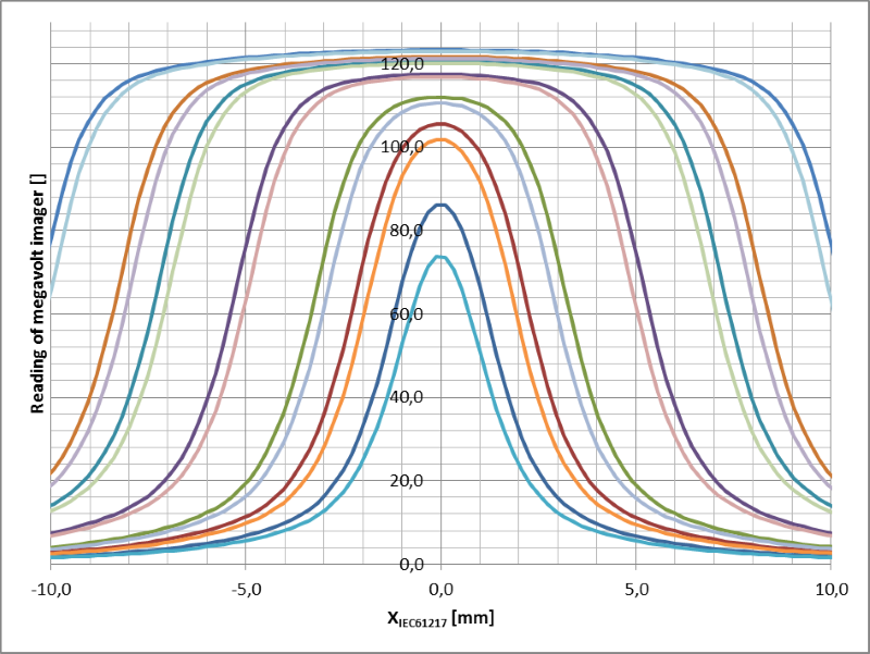
Actual radiation beam profiles of ‘closed’ and ‘opened’ collimation for drive positions: (2, 4, 6, 10, 14, 16 and 20) mm with ’Varian Standard 120M’ are presented in figure 1.
An average slack for studied collimators are: 0.6 mm for ’Varian Standard 120M’, 0.6 mm for ’High Definition MLC’, 0.9 mm for Halcyon/’Distal MLC’ and 1.3 mm for Halcyon/’Proximal MLC’. The slack is found independent of the drive position.

Figure 1: Actual beam profiles for ‘closed’ and ‘opened’ collimation and drive positions: (2, 4, 6, 10, 14, 16 and 20) mm with ’Varian Standard 120M’ MLC .
Conclusion
We have demonstrated that the proposed method can be used to determine mechanical slack of a multileaf collimator. Slack has been found to be device dependent.